 5 components covered
Field manual · Fundamentals
Reading appliance wiring diagrams and tech sheets
Covers: Ladder/schematic diagrams, wiring (pictorial) diagrams, strip circuits and tech sheets found inside US residential appliances
Most appliances carry a tech sheet behind a panel, under the top, inside the console or taped to the back. It holds the schematic, component values, test modes and error codes for that model. Being able to read it fast is what separates a diagnosis from a guess. This chapter explains the conventions; it does not reproduce any manufacturer's sheet.
Safety first
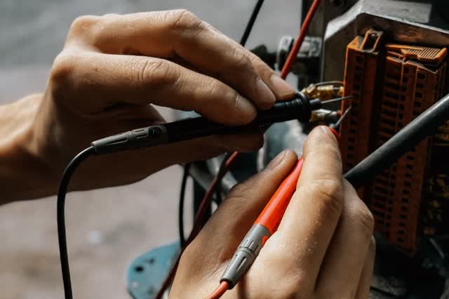
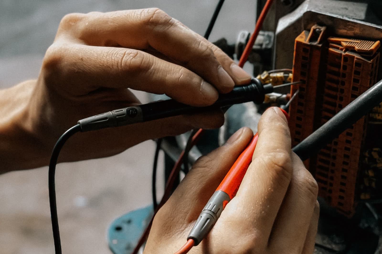
- Back-probing connectors on a live board is a caution step: keep probes from bridging adjacent pins
- Treat every rung as live until you have verified 0 V
How it works
A schematic (ladder) shows how current flows: the supply rails run along the top or sides, and each rung is one path through switches to a load. A wiring (pictorial) diagram shows where the wires physically run, with connector and pin numbers. Use the schematic to understand logic, the pictorial to find the wire.
On a 120 V appliance, L1 is the hot conductor and N is neutral; loads sit between them. On a 120/240 V appliance (electric dryer, range), the 240 V heater sits between L1 and L2, while 120 V parts (motor, timer, light, control) run from one leg to neutral.
Switches are drawn in their resting (de-energized, door-open or cold) state unless the sheet says otherwise. Thermostats and thermal fuses are drawn closed when cold; door switches are usually drawn open.
Connectors are labelled by plug and pin (for example a board connector ID plus pin number). Wire colors are abbreviated (BK, WH, RD, BU, OR, etc.); tracer stripes are shown as a second color.
A strip circuit is a way to isolate one function: follow only the path that powers the failing load from L1 to N (or L2), list every switch, connector and fuse in that path, and test each in order. The open part is somewhere between the last point with voltage and the first point without it.
Components & tests
Unlock all 5 components, specs, service mode and teardown
Full library + AI assistant for $34.90, one time.
Get lifetime accessOfficial manufacturer documentation
Always confirm values against the tech sheet for the exact model.
OnCall Tech is a reference tool for trained technicians and can make mistakes. Always disconnect power and confirm with the manufacturer's documentation before you work. © 2026 OnCall Tech. Original content; not a reproduction of any manufacturer document.Generic part photos (not of this brand): Hands holding multimeter probes on motor wiring terminals by Bulat843, Pexels License